Introduction
This project combines a SG Labs V2 transverter and a PE1RKI 25W power amplifier for field day operation with a 70cm transceiver. This project was driven by John VK4MJF. The research, component selection, and mechanical assembly, with some review, was John’s handy work. My role was inspection, revision, and testing. This time, unlike the 5.7GHz 20W amplifier without a “magic Smoke” letting phase. 🙂
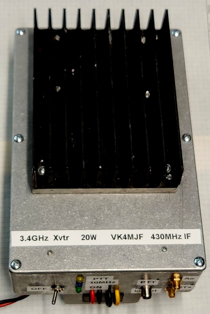
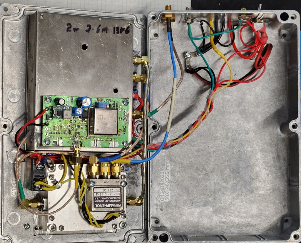
The transverter and amplifier were mounted in the lid of a diecast aluminium enclosure 222 x 146 x 55mm with a 10MHz OCXO reference, antenna changeover relay, and power relay. A DC-DC converter, 24V supply for amplifier and coaxial relay, is mounted on the bottom of the enclosure.
SG Labs Transverter V2
SG Labs is a Bulgarian manufacturer producing a range of amateur radio transceivers and power amplifiers as well as industrial radio solutions. Their web pages do not to reflect all products. email contact info@sg-lab.com appears to be the best way to get current information. A four-page specification and setup manual is provided with the module. Andrew VK3FS has published blogs on their products and his Andrew VK3FS’s web pages provide comprehensive information including field testing and results.
Features
- 430MHz IF (programmable)
- IF input 200mw to 5W max
- Frequency range 3380 to 3480MHz (VK 3398)
- 12v DC nominal power supply
- Power Output 2.5 W
- Low noise figure – GaAs pHEMT input stage
- High performance UP/DOWN converters
- Hi stability internal TCXO
- Provision for 10MHz external reference
- Internal TX/RX switch
- Split TX/RX option
- Internal direct coupler
- Output SWR indicator (bi colour LED)
- Optimal input power indicator (bi colour LED)
- RF vox or PTT input
- External PTT on RF detect
- Integrated sequencer
- Link selectable LO / IF frequencies
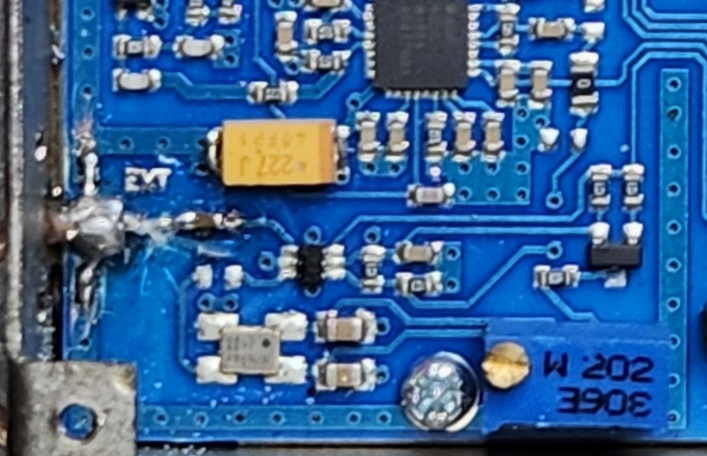
Phone jack connectors are provided for the supply and PTT. These were removed and feedthroughs fitted. The 0R link was rotated to provide split RX/TX mode to drive the external power amplifier.
The RF Vox Hold Time should be set to long for SSB operation. Note the RF vox not only applies PTT to the transverter but also provides an open collector ground for PTT to external devices, such as the power amplifier and external antenna changeover relay. Note the Vox Hold Time is applied to the external PTT release.
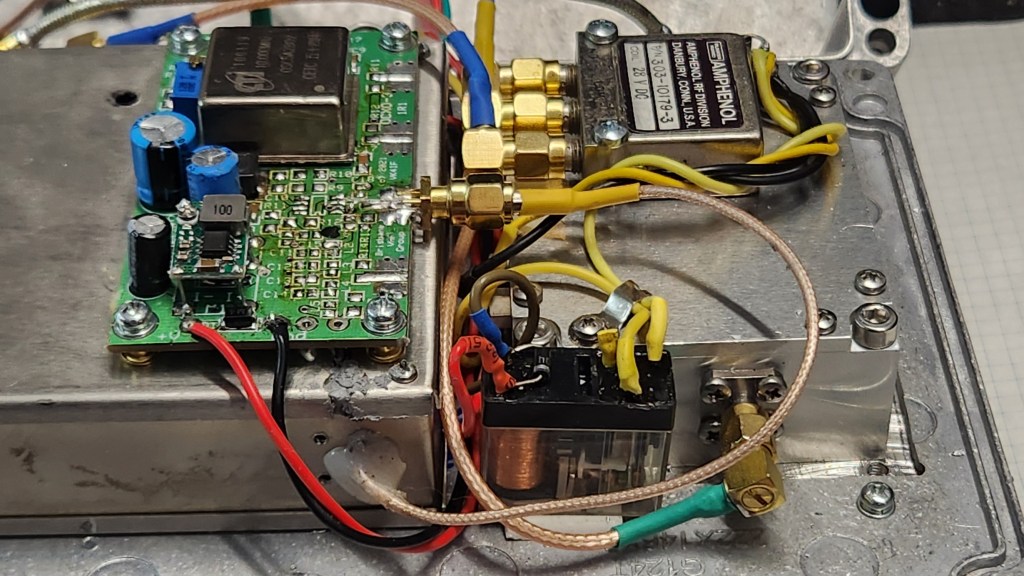
Electronic switching between internal and external frequency reference is provided. Due to enclosure constraining connection to the external reference SMA connector, the connector was removed, and a coax cable was terminated on the PCB. As the OCXO-1 is mounted with the transverter, the external 10MHz was permanently linked to the PIN switch output and the internal reference link removed (See photo).
Links are provided to selectable local oscillator for IF and RF frequencies. For 3398 MHz (VK narrow band operation), 2963 MHz LO provides 435 MHz IF. Refer VK3FS pages for details.
Power Amplifier
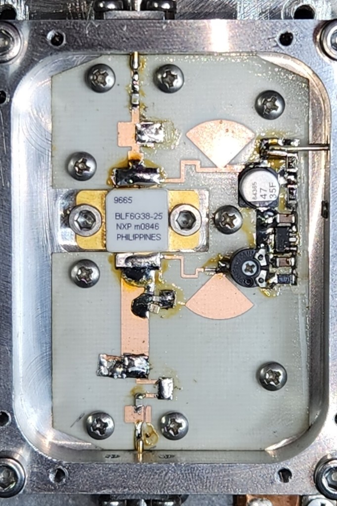
The 25W amplifier is one of Bert PE1RKI’s range. This model isn’t listed on his web pages and no manual is published. Application details were gathered through a set of question and answer emails. Bert was helpful and responded promptly.
The amplifier is well built and housed in a beautifully milled enclosure with good weight lid, screwed on in eight places. A microwave absorbent pad is fitted to the lid to minimize the risk of instability in the cavity of the enclosure.
After initial testing, the amplifier stopped responding to drive. Close mechanical examination showed the soldering may have been better around the input, output, and matching capacitors. The latter was straightened and resoldered with a heat gun. The input and output coupling capacitors were replaced with 20pF ATC 100B types. Small changes in the snowflaking were made to confirm these changes had not affected the optimum matching.
The amplifier operated from 24V DC. Bias is regulated and the trim pot allows the quiescent current to be set to the required 750mA. Current at full output and 24V supply is 2A. Driving to higher current is not recommended.
Power Supply
The combined transverter, 10MHz reference, and amplifier operates from 13.8V, lead acid battery for field operation. A 13.8V 5A bench supply was used for the testing. A 10A step-up converter mounted on the base of the enclosure provides +24V. After a failure of this module when the input voltage was PTT switched, it is recommended to run the converter continuously and tolerate the standing current ( 0.4A approx).
The 10MHz reference is supplied directly from the external battery / fuse to allow keep warm at low current 200mA when transverter is not in use. A flashing blue LED shows the reference is powered. A miniature SPST switch controls the battery supply to the transverter and 24V converter. A green LED indicates supply is available. A yellow LED is mounted with these LEDs to indicate PTT is applied directly or on RF vox.
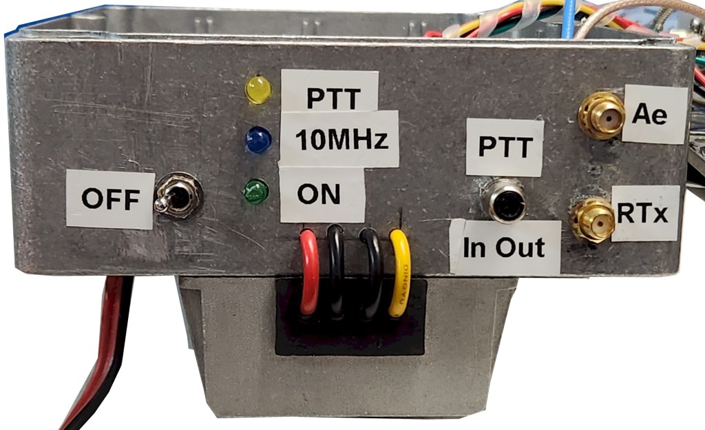
A 10A single pole relay with 12V coil operates on PTT, to provide 24V for the amplifier and coaxial changeover relay.
Testing
Due to a self-imposed frequency limit of 1GHz (1970s oath), my workshop test equipment is limited at microwave frequencies. My ever-reliable HP432 power meter and thermometer sensor with a set of coaxial attenuators provide accurate power and cable loss measurements. A TinySA was used to confirm IF, LO, and output frequencies, provide an alternative power measurement, and provide a signal generator for receiver tests. A NanoVNA V2+ provides loss and reflection coefficient testing up to 2.5GHz but performance is degraded above that (Ultra mode). A DigiLO and broadband amplifier provides a signal source up to 20dBm. A Baofeng UV hand-held, 1 and 5W drive at 430 MHz, provides IF transmit and receive.
Initially, a 10dB pad was inserted between the transverter and the amplifier input. This was expected to drive the amplifier to full power with maximum transverter output. Due to cable losses a better compromise was found to be direct connection with lower transceiver Tx Gain setting (500mW drive for 25W output). The transverter SWR indicator (red/green LED) also seemed happier with this configuration.
The Tx Gain setting was investigated with 1 W and 5W from the FM handheld. The transverter provides a red/green LED as an indication of correct input level. 1W with Tx Gain set for full output from the amplifier was found to work well. With 5W input, the transverter appeared to be saturated and the maximum current remained below the 2.5A advised by PE1KRI. With 10dB attenuation inserted on the IF input, the RF Vox continued to perform consistently.
Caution: The IF transmit power should be set using the input LED while keeping the output of the amplifier below its saturated 25W. A radio with less than 5W output or with a reliable maximum power setting should be used. The transverter input may be damaged by input level at or over 5W continuously.
Coaxial relay and cable losses from the amplifier measured at 1dB approximately. 20W was available at the system output connector.
Test equipment limitations meant the absolute sensitivity of the transverter could not be measured. The Tiny SA with a string of coaxial attenuators confirmed the receiver with the transverter provided gain. The receiver gain was set mid-range (0-10dB) for field testing.
Noise figure is expected to approach 2.5dB (transverter in split mode plus coaxial relay and cable losses – mounted at dish feed). When time permits, the noise figure of the system is to be confirmed to the IF with the HP8970 noise figure meter and its 18GHz noise source.
Conclusion
This system provides an economic solution for operation on 3.4GHz band. Receive performance is expected to be good. With a 40-50cm dish, EIRP over 5kW should be obtained. Frequency accuracy and stability with an IF transceiver such as an Icom IC705, IC905, IC9700 should be excellent.
