Introduction
This project involved selection and assembly of the components for a 5.7GHz amplifier for an Icom IC905 transceiver. My role was inspection, test, and commissioning but progressed to “letting the magic smoke out” and finally recovering for a successful outcome.
The eBay purchased module YPM5820S was manufactured in China by Szhuashi, who makes an extensive range of WIFI (2.4 & 5.7GHz) boosters, power amplifiers, and jammers. There is little data provided by the manufacturer, but their low price has created interest amongst amateur operators world-wide. Their investigation and sharing are producing an excellent pool of information to assist selection and application.
Design
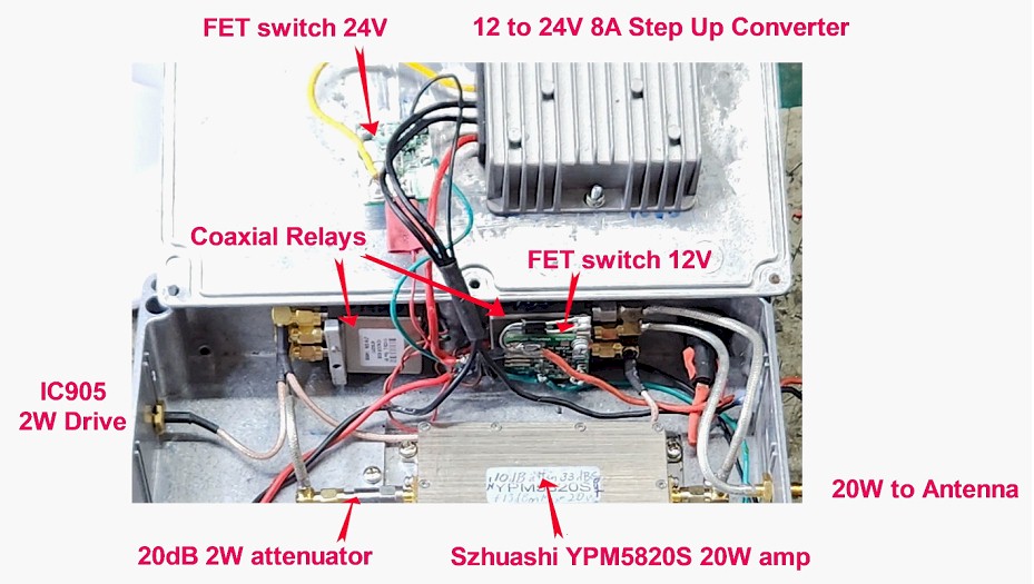
The photo shows the components selected for the amplifier. The YPM5820S amplifier and the Dowkey SMA coaxial relays operate on 24Vdc. An automotive 12 to 24V DC-DC converter was selected to provide the 24Vdc. FET switches provided control from the PTT.
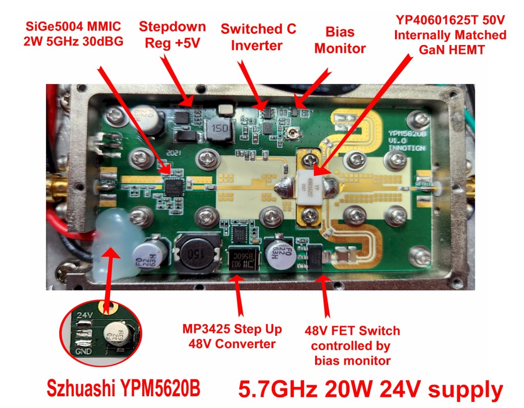
Lifting the covers of the YPM5820S amplifier revealed a Se5004 MMIC (Skyworks 5GHz 32dBG 26dBm max output) driving a YP40601625T (Szhuashi 4 to 6GHz 20W 15dBG 50V internally matched GaN HEMT). An 8dB masking attenuator is fitted prior to the Se5004L to improve the input SWR. In this sample, no snowflake matching had been applied to the FET. The overall gain is specified as 43dBG (0dBm drive for 20W output).
Analysis of other circuitry in the module showed a step-down regulator providing +5V for the Se5004L. The +5V is used as input to a capacitive pump converter for the negative bias of output FET. A monitor for the bias controls a P channel FET protecting the output FET from a failed bias condition. An unusual aspect of the design is a MP3425 step-up converter providing 48Vdc >1A as required by the output FET.
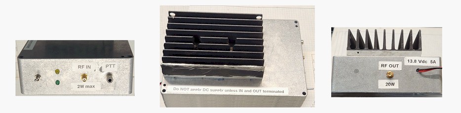
The amplifier uses a 1.2mm multilayer printed circuit PCB mounted in a milled enclosure. SMA female connectors are used for input and output. The DC supply is connected to the edge of the PCB at a milled slot. Multiple M3 screws secure the PCB to the enclosure to ensure correct operation of the printed microstrip lines, matching, and isolation inductors.
Testing
First problem in a workshop with a 1GHz ceiling was finding suitable test equipment to run-up the amplifier. For previous experimenting with microwave transverters and investigation of WIFI boosters I produced low power signal sources (< 20dBm digital PLL & multipliers). Tiny SA and NanoVNA allowed testing of coax cables and coaxial relays at up to 2.5GHz. A dummy load and suitable attenuators to handle the specified 20W at 5.7GHz were tested at 2.5GHz for use ahead of the HP432 power meter and thermometer power head.
Many of the coax cables had been assembled with RG412 and crimp SMA female connectors. In retrospect the cable was not ideal for the frequency and the crimp connectors proved unreliable with failures in the connection of the braid. Progressively the cables were tested, rejected and replaced with RG402 tin-soaked braided PTFE dielectric and silver-plated copper inner with solder on SMA female connectors. Most connectors were right-angle types, as they were in-hand. Straight types may have been a better option for the frequency.
The receive path eventually tested reliably with each SMA coaxial relay measuring at 1 dB insertion loss, each. A little higher than expected.
Power Supply
A 12 to 24V automotive type DC-DC converter had been chosen with FET switch for PTT switching. As the idle current of the DC-DC converter was high, the FET switch controlled the supply to the DC-DC converter.
The FET switch PCB (W6PQL) is on the smallest footprint and provides little pad area for connections. The design has the tab of the FET as the output. Better connection and mechanical mounting of the switch module may have been provided on a PCB at least twice the size.
PTT test showed the output capacitors in DC-DC converter held up the supply unacceptably long. Another FET switch was inserted after the converter.
Transmit Test
The amplifier was terminated in 35dB attenuation (10dB 5W, 20dB 2w and 5dB 1m RG316 cable) to the HP432 power meter.
With 24V applied to the amplifier, the quiescent current was 1.4A. A DigiPLL was setup for 5760MHz. At -10dBm drive, the gain of the amplifier was the specified 43dB.
The 20dB coaxial attenuator was inserted in the input of the amplifier and the amplifier setup for drive from the IC905. With PTT applied and low power from the IC905, the amplifier current increased and output power increased.
Increasing the drive from the IC905, the amplifier current increased to 2A, but before the power was measured, the “magic smoke” escaped.
The post-mortem showed the output FET, the Pch FET, and the MP3425 were short. The reason for the failure was not clear. The test was conducted under time constraints. Something in the test configuration (SWR, damaged cable, overdrive by IC905) may have contributed. There may not have been enough respect paid to the high gain of the amplifier. With 43dB gain, 20dB attenuator, and cabling losses, less than 100mW from IC905 was required to drive the amplifier to 20W.
Repair
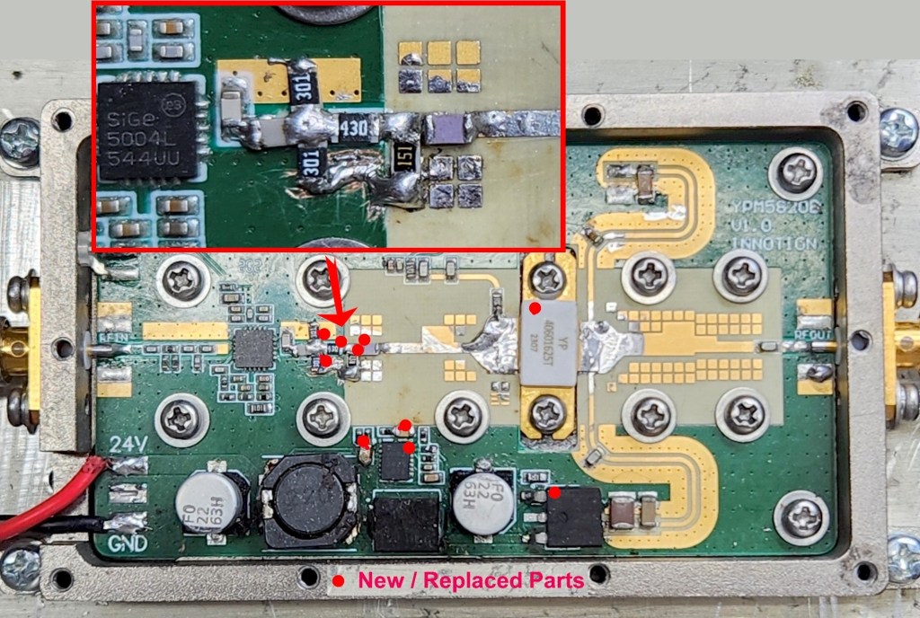
The output FET was removed from the PCB, and its input and output microstrip joined with a 3mm strip of copper. The Se5004 tested OK.
A replacement YP40605820 was ordered from Szhuashi Store on eBay and MP3524 from Monolithic Power Solutions (direct purchase required registration – they were very helpful).
The components around the MP3524 were measured. The values matched the evaluation board except for the sense resistors were lower values. After replacement of MP3524 and Pch FET, supply to the output FET was confirmed as 48V at >1A. Bias protection by the bias monitor and Pch FET were normal.
To reduce the risk of overdriving the output FET when using the IC905, a 10dB attenuator was added after the Se5004. The track at the output of the Se5004 was cut to fit a new 20pF 0604 capacitor. Two 300R 1208 resistors were fitted to ground. A 43R 1208 mounted in place of the original coupling capacitor. A 150R 1208 to ground before another cut to the PCB and the original coupling capacitor was fitted (see photo).
More Smoke
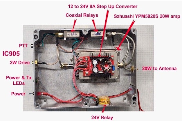
While confirming the amplifier’s gain was normal, the 12-24V DC-DC converter quietly and invisibility released its “magic smoke” (short circuit input). A replacement converter (150W eBay) was mounted on the lid of the amplifier module. A “real” 10A relay was fitted to switch the 24V supply to the amplifier. The DC wiring was replaced with the addition of a power switch and 5mm LEDs showing power and PTT. The Anderson mini connectors and the inline fuse were replaced on a new length of red/black twin.
Final Test
A dig through the workshop found a HP 798C 10dB 3.7 to 8.3GHz directional coupler and a 50W Philco dummy load. The combination provided a load with SWR <1.2:1. With SMA coaxial attenuators and the 1m RG316 cable, the HP432 power meter was connected for measurement up to 100W. A far better test configuration than previously used.
With the IC905 connected, the SWR and attenuation on the through receive path was checked. SWR <1.2:1 and attenuation of each SMA coaxial relay and coax tail being 1dB (a little higher than expected). With PTT applied the amp with its DC-DC converter drew 2A at 13.8V.
The power output from the IC905 was increased. The amp operated as expected. 20W output at just less than 1W from the IC905. Current drawn at 13.8V was 4A.
Final Observations
This project was full of disasters. These were in the main due to the lack of information provided by the manufacturer of the amplifier module and the novelty (for me) of testing at 5.7GHz.
Since this project started, much information has been shared on group.io Moon-Net (Moon-Net@groups.io | Messages) about WIFI extender and jammer modules.
Depending on the negotiate price the 50W Jammer module is better than this 20W amplifier. The 50W FET runs from 24Vdc, thus the complexity of the MP4325 DC_DC converter is avoided.
Don’t pay marked price – my offers of 50% have been accepted.
