Introduction
The Icom IC9700 provides a single “SEND” signal on the ACC socket. Many operators prefer a separate PTT to each of their amplifiers / LNAs.
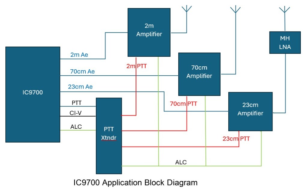
This “box” monitors the CI-V serial communications from the 3.5mm jack to determine the band in operation by the MAIN and reflects the radio PTT to the box’s RCA jack the band in use.
The box connects to the radio by the ACC via an 8pin DIN cable and the 3.5mm CI-V jack. This connection provides the supply for the box and provides an optional connection of the ALC from each amplifier to the radio.
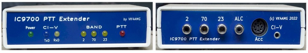
Front panel LEDs indicate CI-V data states, band-in-use, radio PTT state.
The box is designed to avoid conflict with other applications using the CI-V bus (either 3.5mm or USB). Selecting “transceiver” option in the CI-V menu ensure regular updates of the radio frequency to the box.
The box is housed in a polyester instrument enclosure. The font panel carries the status LEDs. The rear panel carries a 3.5mm phone jack for CI_V, an 8 pin DIN socket, three sets for RCA jacks providing PTT connections for the three bands, and a RCA jack connected to the ALC on the Acc socket.
Enclosure
The electronics uses leaded components mounted on a single sided printed circuit. The microprocessor is an Arduino Nano connected by headers. The PCB is mounted on the base of a 140 x 110 x 35mm polyester instrument enclosure. The front panel carries the power and status LEDs.
The rear panel carries the 3.5mm phone jack for the 5V CI-V serial data, an 8pin DIN socket with pinouts matching the IC9700, and dual RCA female jacks for ALC and PTT for the three bands. An RCA female jack provides connection to the IC9700 ALC pin on the ACC connector.
Operation
When the radio is turned on, the Box is powered via the ACC cable. A Power LED indicates the Box is operating. After initialisation, the front panel LEDs are flashed in turn. No outputs are operated during initialisation. Band-in-use LEDs will be extinguished until valid CI-V band / frequency messages are decoded. If the PTT is applied by the radio when the Box initialises, the red PTT will flash rapidly as a warning, nothing further will occur until the PTT is removed.
CI-V activity is indicated by the flashing the TxD and RxD LEDs. Once band or frequency information is decoded, the band-in-use by transceiver is indicated on one of three yellow LEDs. Application of the PTT will then be indicated on the red PTT LED and the PTT output for the operating band will be grounded.
The box includes a ALC holdoff function. When PTT is not applied or if the PTT is applied but the band has not been decoded, maximum ALC voltage is applied to the IC9700 and ALC connected amplifiers. This prevents the radio from transmitting unless the CI-V and the Extender Box are working correctly. IC9700 RF output is then not active for 100ms after PTT is applied. This function prevents the possibility of RF output spikes and holds off the RF power output until PTT and changeover functions are active.
On removal of the PTT, the red PTT LED will extinguish. Any change of band / frequency will be indicated on the yellow “band-in-use” LEDs. If no valid band /frequency CI-V messages are decoded for 30 seconds, the extender will poll the IC9700 for the “band-in-use”. If a valid status is not received from the IC9700, the yellow “band-in-use” LEDs will flash, and no further output operations will occur until normal operation is established.
In the absence of PTT and band broadcasts from the IC9700, the extender will poll the IC9700 for the “band-in-use” every 30 seconds. This means the PTT Extender is ready to apply the PTT for the appropriate band. 10mS PTT debounce is applied to the PTT input signal.
NOTE: The USB CI-V and remote control must be uncoupled in the IC9700 connections menu. That is “remote control” jack communicates with PTT Extender, USB CI-V communicates with computer applications.
Specification
Power supply 13.8 Vdc 100mA max from IC9700 ACC pin 2
Baud rate 19200 8, n, 1 link. IC9700 configuration must be set to match.
CIV Icom IC-R8600 CI-V Reference Guide.
PTT output V max up to 24 Vdc. Active low 1V @100mA
Latency < 10mS key down key up.
ALC holdoff Delay of IC9700 power output provided as sequencing of active PA /LNA
100 ms.
Kit and assembled/tested versions of the IC9700 PTT Extender are available at City of Brisbane Radio Society SHOP
