This project describes provision of an RF tap, for an external SDR and waterfall / spectrum analyser
programs, for the all bands of the Icom IC7300 transceivers. As I do not own an IC7300, the analysis is based on the Icom Service Manual. Please refer RF Tap for 2m IC746Pro / IC7400 for the detail of the technique and construction of the splitter amplifier.
An RF tap fitted internal to the transceiver provides a safe connection to extract the RF signal without degrading the receiver in the radio. Most Icom transceiver provide a convenient location to apply the RF tap.
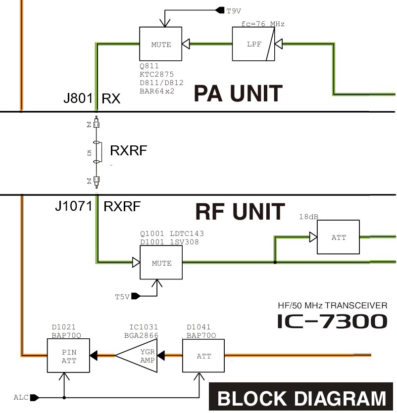
The PA Unit provides the antenna low pass filter and antenna changeover. The RF UNit provides the receiver input protection, receiver front end tuning to preamp / attenuator and the remaining receiver functions. Coax cable designated RXRF interconnect the PA Unit and RF Unit.
.
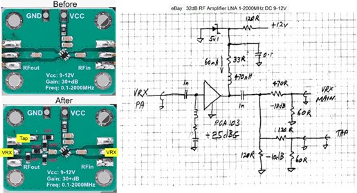
A low cost eBay LNA 0.05-4G NF=0.6dB RF Amplifier Ultra-Low Noise High Linearity FM HF VHF/UHF, is modified to split the receiver RF into two paths. The Vcc series resistor is increased to allow operation of the LNA from 13.8V. A 5V Zener may be used for additional supply protection. Two simple attenuators split the amplifier output. One feeds the 2m receiver preamp (VRX) and one is fed to a rear panel SMA.
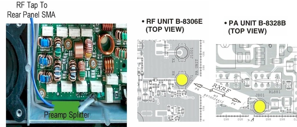
The board layouts show the location of the interconnecting RXRF jacks. A suitable location for the splitter amplifier is fitted to the front wall of the PA Unit enclosure or on the central divider wall near J1701. If an alternate location is preferred, a replacement cable (crimp connectors are Taiko Denki TMP-K01X-A1) may needed.
The RF Tap cable may be brought out the rear panel of the radio through a suitable hole drilled under the Tuner connector. The supply for the splitter amplifier may be drawn from the tuner connector wiring.
