While experimenting with combining ALC from 2m and 70cm SSPA for control of an
IC910H, the dreaded ‘spike on PTT’ was identified and quickly killed two FETs in the NEC
UHF amplifier module.
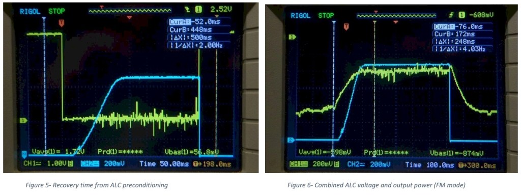
Figure 1 shows a full power spike of short duration occurring when the transmitter was
terminated in a dummy load. The waveform is captured using a directional coupler and RF
power detector. Yellow trace is PTT and blue, RF output (FM mode).
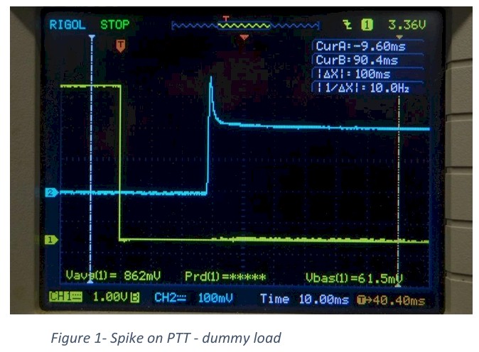
The spike (Figure 2) changed to 20ms duration full power when the transmitter was driving the
70cm SSPA with its sequencing and protection. RF power control has been set to a lower level than
that in Figure 1. What part of this spike appeared at the input to the amplifier module was not
investigated. Any part is potentially a FET killer.

As the behaviour of the ALC on the IC910H was found to be different from the other ICOM
radios where external ALC had been applied, the operation of the IC910H external ALC was
investigated.

The gain of the transmit IF amplifier is controlled to set the output power level, provide SWR
protection, and provide PA current protection. As the IC910H has three power amplifiers (2m,
70cm, and 23cm) the monitoring signals (forward power, reflected power, and PA current) are
combined before being fed to the amplifiers producing the negative ALC voltage. The outputs from
the three ALC amplifiers are diode combined. The external ALC is applied directly to the combined
point, gate one of the Tx IF amplifier. Examination of the 3SK131 data sheet shows a gain change of
over 20dB may be achieved with a change from -0.4 to -1.2 volts. Application of an ALC voltage
outside this range may prevent normal operation of the Tx IF amplifier (No transmitter output may
be the result).
The spike in output power appears to be due to the indeterminant state of the control signals and
the resulting ALC voltage at the instant of PTT. The time constant associated the R & C of the
bypass circuits on the gate of the Tx IF amplifier causes a delay on gain reduction of this stage.
Any components on the external ALC line (pin 8 of ACC connector) will also affect the application of
the output power setting ALC. Any external ALC signals should be applied via a diode and any
impedance applied to the external ALC pin should be high impedance. A value of 220K was used to
set the time constant of the ALC to around 50 ms.
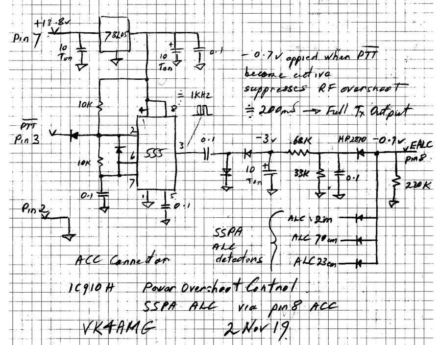
Figure 4 is the schematic of my external ALC preconditioning and combiner for the ALC from the
ALC of a SSPA for each band. The preconditioning aims to control the Tx IF amplifier from the
instant of PTT rather than leave the gains and hence power output indeterminant until the internal
ALC protection and power control is established.
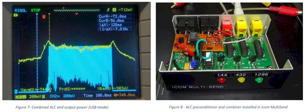
A small vero board prototype of the ALC preconditioner and combiner was installed in a Icom Milti-
Send (VK4GHZ) case. The combination provides PTT and ALC connections from 2m, 70cm, and
23cm SSPA to the IC910H.